Industry Figure | Berkeley | Back to Jeep Cherokee
Main | Rear Lift | Front Lift | Quick Disconnects | Side Effects | AAL & Blocks | Bent Leafs
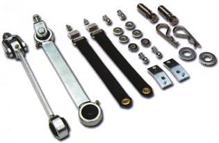
Cherokee 3.5" Lift Installation - Quick Disconnects
I write these web pages partly for the fame and glory, but mostly because I care about you, the Cherokee 'wheeler. (Not really, I just thought it sounded funny.) That's why I spend so much time bringing you top notch stuff like the never-before-seen images which I refer to at the beginning of Part Two below. Read on, fortunate XJ owner.
Longer anti-sway bar disconnects are a must after lifting the Cherokee. And as long as you are going to replace the link, you might as well get a quick disconnect. Articulation is one of the keys to successful off-roading, and the anti-sway bar is the enemy of articulation. Depending on your lift height, you'll purchase a different length "disco." The original (abridged) written instructions from TeraFlex are reproduced below in italic and are indented. My comments and links to images are inserted throughout.
Installation Instructions for New Generation Quick Disconnects
Part One
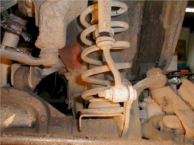
Prior to starting the installation, please remove stock sway bar links.
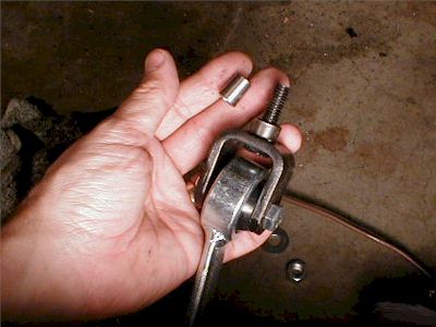
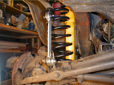
We are in the middle of the front-end lift, so our XJ is already in the air and the wheels are off. To remove the stock anti-sway bar links, on each side, loosen both nuts, but don't disconnect the bottom until the top nut is loose. You'll need the link connected to the original stud in order to loosen the top nut. (A milestone for my son: here he removes the nut getting grease on his hands for the first time.) I was worried about removing the lower connecting stud, but it was loose (in the permanent bracket) already. If I remember correctly, the stud takes about a T55 torx wrench. I didn't have one, so I used locking pliers to hold the bolt head.
Step 1
After removing the sway bar links, identify the left and right quick disconnect. One way to tell is that the bolt head will point away from the vehicle in its final position.
In other words, looking at the disconnect from the side of the vehicle, you will see the bolt head at the top.
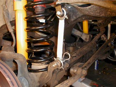
If you are doing the quick disconnect installation with the vehicle in the air, realize that when the axle drops, it swings toward the driver's side of the vehicle. That said, the sway bar links won't be lined up the same way as when the weight of the XJ is on the axle. Normally, the discos will slant down evenly (in other words, at the same angle) toward the outside. With the axle extended, the passenger side disco will be hanging straight down and the driver side disco will be angled radically down toward the outside.
Place the round spacer ring on the threaded bracket bolt.
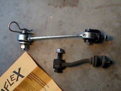
There are two types of "round spacer rings" (I call them bushings) included in the kit. My '90 XJ needs the cylindrical style. I understand--from folks more knowledgeable than myself--that the conical style is used in the Grand Cherokee (ZJ) and the newer model XJs. In the image, the conical bushing is on my fingers and the cylindrical bushing is on the bolt. While they're both off, compare the old and new links.
Once the assembly has been inserted into place, make sure that the grease zerk points downward away from the vehicle. Add the flat washer and nut and secure.
The top grease zerk (is zerk really a word?) points down and toward the front. Once tightened, the bracket should be secure. Mine wasn't tight and was actually rattling on the passenger side. It turns out that the bushing was a little too thick (or was the anti-sway bar eye that was too thin?). Of course, I snapped the bolt before I figured that out. Read more about my over-tightening adventure on the side effects page.
Step 2
Attach the sway bar connecting stud to the lower mount bracket by inserting the stainless steel stud in the hole vacated by the sway bar arm and securing with lock washer and nut. Be sure that the threaded portion of the stud points away from the vehicle.
Conversely, the rounded end of the new stanless steel stud points toward the center of the vehicle. This can get confusing when the car is up in the air and the axle has shifted from its normal, centered position.
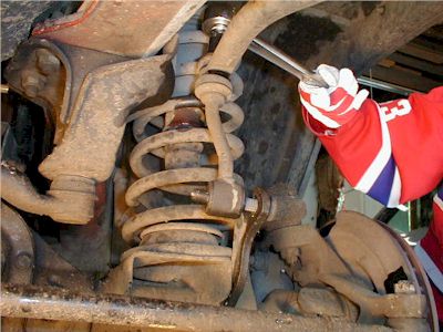
Step 3
Use the pin for leverage when tightening the nut with a 3/4" wrench.
Step 4
Attach the sway bar arm by sliding the polyurethane bushing onto the lower stainless steel stud. The use of lubricant such as WD-40 will make this much easier.
This step would have been a breeze except that on my XJ, the steering stabilizer bracket interferes with the disconnect stud. The space between them isn't big enough to slide on the quick disconnect. I discuss this further and provide my solution on the side effects page.
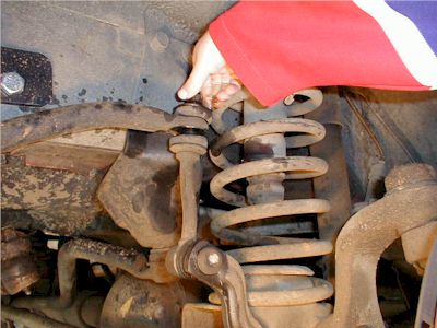
Step 5
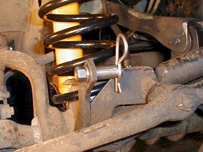
Secure the quick disconnect by placing the washer on the side opposite the bolt and insert pin into the stud. NOTE: This photo illustrates how the front axle will shift to the driver's side when the suspension is fully extended by a hoist. You may wish to connect the components with the vehicle on the ground.
I had a tough time getting the cotter pins through the holes; more accurately, it wasn't possible. I could get the pin into the stud, but not out, because it would hang up against the flat washer. After scratching my head for a few minutes, I decided to file the ends of the cotter pins so that each would have a little ramp. It worked beautifully. The "sharp" end of the pin clears and--with a little grunting--pushes the washer further on and the pin slides all the way in. Now my cotter pins are asymmetrical, but more functional.
My troubles might have been due to my ignoring the "note" above. It might have been easier to insert the pins with the vehicle on the ground, but you don't always have that option on the trail. The ramped pin-end will pay off, I'm sure.
Part Two
Step 1
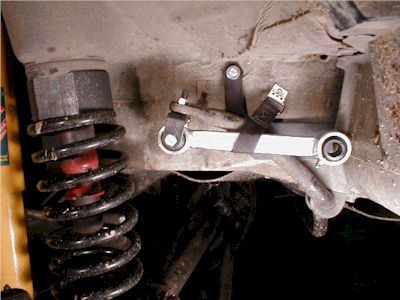
The next step involves installation of the retention strap used to secure the sway bar when disconnected. Drill the hole where the retention strap will be attached. The photograph shows one possible location.
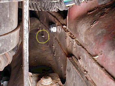
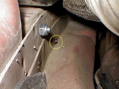
If you are sitting in front of the wheel well opening thinking about drilling your first hole, no doubt you are thinking to yourself, "I wonder what's on the other side of this metal. Am I going to drill a hole through something really expensive?" Good question. I have the answer here and here. These are images I managed--with lots of trial and error--to capture for you. They show the exit locations on both sides of the vehicle for the larger strap-bolt hole and the smaller hook-screw hole. It's easy to see the larger bolt. Look carefully for the little screw which is below and behind the bolt (highlighted in the large image with a yellow circle). On my vehicle, there's nothing in the way of the unforgiving drill bits. Double check your vehicle with a small mirror (my wife thinks it's really funny that I got grease on her makeup mirror) and a strong flashlight. Use a 1/4" bit for the larger strap-bolt holes.
Step 2
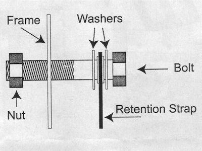
Place one washer on each side of the grommet located on the upper end of the retention strap and insert the bolt. Please refer to the diagram.
Step 3
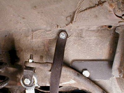
Tighten the bolt to secure the retention strap.
You'll be hugging the fender and abusing your arm (getting it inside the engine compartment and past all the stuff in the way) during this step. I used an open-ended 7/16" wrench on the inside nut and a 7/16" socket with a small extension on the outside bolt. It helped to move the battery a little before tightening the bolt on the passenger side.
Step 4
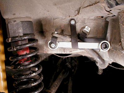
Now, locate and mark the proper position for the retention strap hook. Be sure to allow enough freedom in the strap to remove the strap from the hook.
When positioning the second side, make sure the first side is hooked up. Ideally, you'll want the tension on both straps to be equal.
Step 5
Drill the hole marked in Step 4.
Step 6
Attach the retention strap hook to the vehicle using the included metal screws.
I drilled the hole for the strap hook using a 7/64" bit, which I hoped wouldn't be too big. No problem. I could barely tighten the screw against the thick unibody steel.
Notes on securing your disconnected sway bars
There are two methods of securing the disconnected sway bars. One method should be stronger but the other is quicker.
Main | Rear Lift | Front Lift | Quick Disconnects | Side Effects | AAL & Blocks | Bent Leafs